LED
Design using CAD.
This tutorial is now complete. Please report any error to Divinderjit Singh Chattrath
Designing LED using Google SketchUp.
The first step is to find a datasheet from any manufacturer. There are many available on internet. So search one using any search engine. You can find one here.
The following picture is an extract from this document that we require.

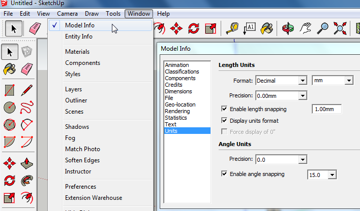
Make sure to set the dimensions as shown below
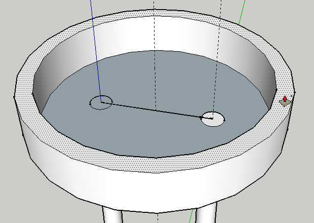
Start by making two wires 50mm in diameter because we are scaling every dimension by a faction of x100. For this you will have to draw a circle of 25 mm radius using the circle tool. Use the tape guide to find the location of the center of second circle from the first circle. By referring to the datasheet, it is found to be 254 mm.

Draw a line joining the midpoints of the two circles at the top and find the midpoint. From there draw a circle of 250 mm radius and another circle of 285 mm radius.


Extrude the annulus by 100mm using the push-pull tool
It is a good idea to first delete the line joining the two centers of the circles formed by top of the wires.
We will now extrude the center part by 733 mm. From the datasheet we know that the total height is 860 mm. we need to make a hemisphere on the top. That will consume the height equal to the radius which is 127 mm (half of 254 mm which is the distance between the center of the two wires). So 860 - 127 = 733 mm. Cool! we used some numeracy skills here!

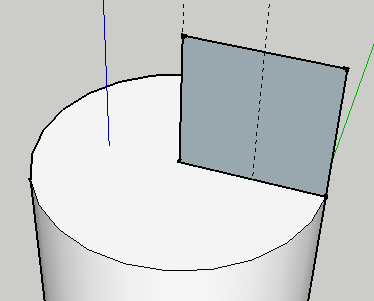
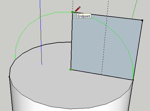
Draw a line parallel to red axis

And a line of same length parallel to blue axis from the center of the top circle.

Use the rectangle to complete the square
Draw a circle

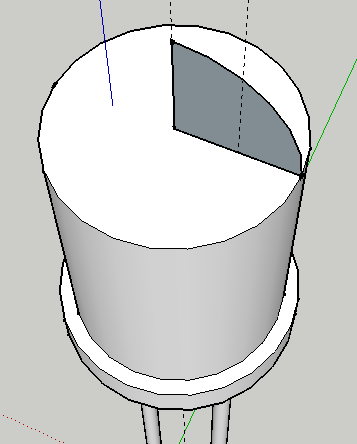
Delete the extra portion in the corner

Another view

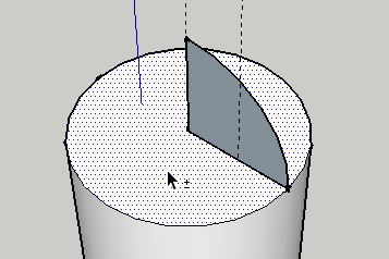
Delete all portions of circle expect the quarter as shown below
Click on the face of the base circle to select it
Now select the follow me tool and click on the quarter circle
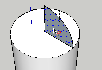
You will get your sphere
Select everything and right click and smooth

Render with the colour of your choice

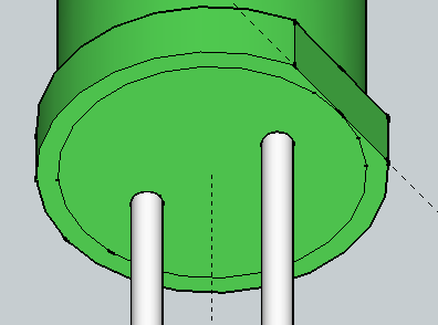
We are almost done, the only thing left is to make the flat surface next to cathode pin (shorter pin).
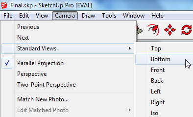
For this we will change some setting first. Choose Camera > Parallel Projection
and the choose Camera > Standard view > Bottom
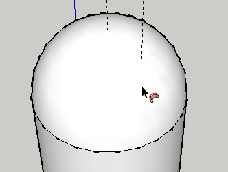
This is what you should see...

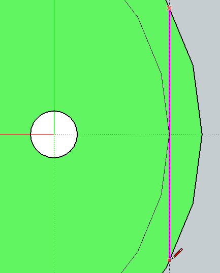
Using a tape measure tool draw a guide which just touches the outer edge of the inner circle as shown below

Draw a line on it which touches the outer circle
Select the push-pull tool and

push up the minor area by 100 mm this will still leave a thin layer

that you will have to delete manually

Click on the line in the middle and delete it too

View from another angle

That concludes the tutorial on LED designing