SketchUp
Design using CAD.
Google SketchUp is a free software and very popular in students. I have used it as an indispensable tool in the Systems Engineering, Electronics and Mechatronics classes. Download from here. You will have to signup and login. You will be asked about your profession. Just choose anything from the drop-down menu and click on the "Submit" button. This should start the download. "Patience is a virtue"
The following pages will showcase some elements that I have designed in this software. It is recommended to follow all tutorials "in order" (do not skip) as there may be features that you need to learn before proceeding to the next tutorial.
Let us learn a few SketchUp basics.
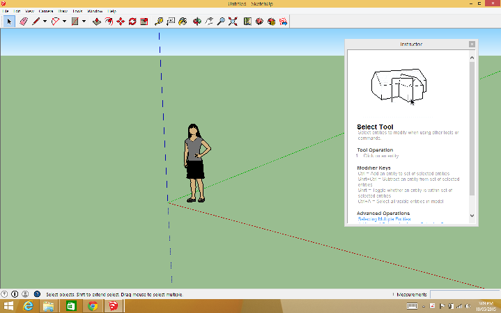
When you first open SketchUp, you are greeted with a window that is similar to the following window. The image of the woman can be something else depending on the template you have chosen in the splash screen. The splash screen keeps changing so I have intentionally avoided it. Its only purpose is to choose a template. It is a good idea to choose the one which suits your need. for example for 3D printing small parts, I would choose the last template called "3D Printing - Millimeters".

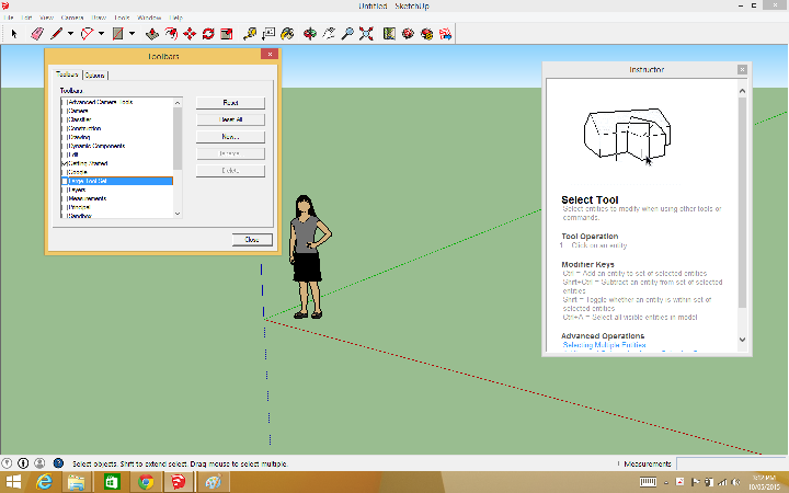
We will do some initial settings. Click on View menu and then click on "Toolbars"

Another window titled "Toolbars" will open. Notice that "Large Tool Box" is not checked.

Check it and click "Close" button
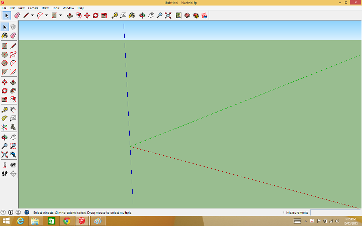
Now you have another set of tools.

Click on the human figure to select it.

Press "Delete" key to get rid of the human image. Also close the instructor window.
Click on "Window" menu and select "Model Info"

a new window called "Model Info" will open.

Set the parameters for "Units" as shown below. Notice that this window does not have any save button. Just click on the red close button on top right corner and the parameters will be saved automatically!

Setting units every time is a good practice but if you do not want to do it again and again then set the default template as "3D printing - Millimeters". It is the last option in the menu option "Window> Preferences > Template".
Time to play with the tools. Following reference card has been obtained from here. You can find a lot of them by searching for "SketchUp reference card" using any search engine.

Note that it will speedup the process to a great deal if you use keyboard shortcuts along with the features provided by a mouse with three buttons.
Let us use some tools
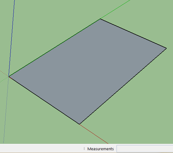
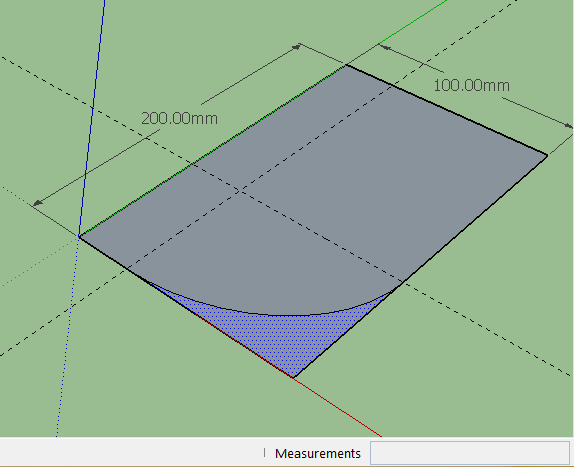
Click r key. This will select the rectangle tool. Hover on the origin. A yellow dot will appear showing that the pointer has snapped with the origin. Click and drag to make a rectangle and carefully leave the mouse without moving it after you have stopped dragging it. Now start typing "100,200" , notice this is being typed in the lower right corner and the cell color has turned pale yellow. Once you hit enter the rectangle will re-size to these dimensions.

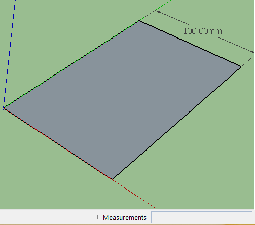
Let us label the dimensions. Click on the "Dimension" tool

Zoom in by scrolling the center mouse button in forward direction, Orbit by pressing the center mouse button and dragging. Pan by pressing the center mouse button and dragging along with pressing the shift key.
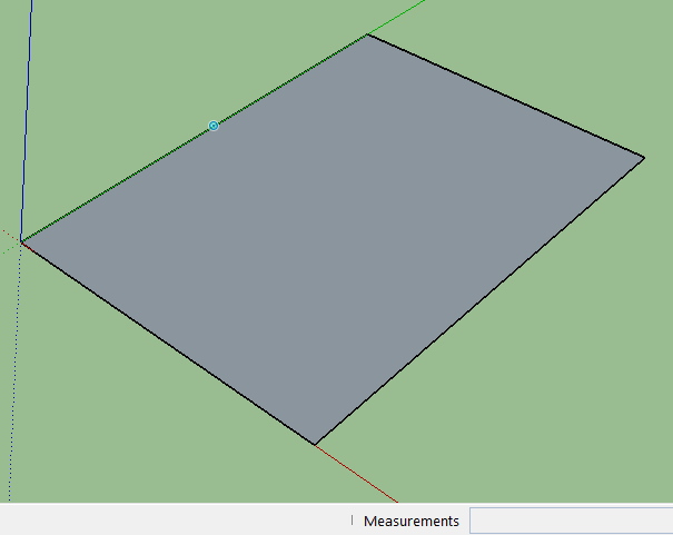
Find the midpoint of one line by hovering around that area (shown as blue dot).
now drag across to other side. Click on the mid point of the other side.

Now drag outwards and click where ever you feel is the correct place to place the dimension.
Alternatively you can click on a line somewhere (not in the middle) and drag it outwards.

You can delete any dimension at any time by right clicking and choosing "Erase" from the popup menu.

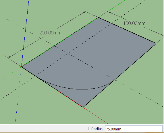
Press t key to bring up the tape measure. This is useful to set guide lines. Say we want to round off one corner so that the curved part is exactly 75 mm from the corner on both sides. So we setup the guide first. just click on one of the lines that make the corner and drag now type 75 and hit enter. Do the same for the other side.

Note that 75 will appear in the lower right corner as length while you are typing. At that time the background color will be pale yellow but once you hit enter it will turn white and the guide will go to the right place.
Now hit the a key this will bring up the arc tool. Click on the points shown by red crosses in any order, then drag outwards. The arc will be formed and at one place it will turn pink.

This is where you click to fix it in place.
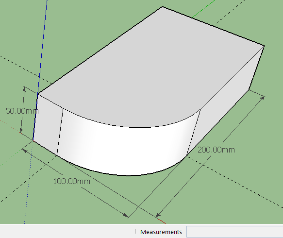
Hit the space bar to bring up the select tool. Click on the outer area ...
...and press delete. Now select the other two lines one by one (or shilt + select both) ...

...and delete them also.

hit the p key to bring up the push/pull tool. click, drag upwards and type 50 and hit enter. Set the dimension of the height and readjust the dimensions.
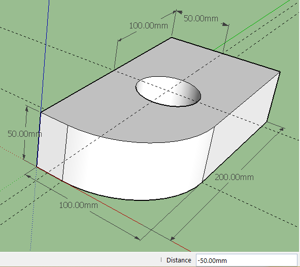
Now hit the t key to bring up the tape guide tool. Make two guide to find the middle point of the surface. Set the two dimensions (100 mm and 50 mm) to show the center. Now hit the c key to bring up the circle tool. Click in the middle and drag outward ...

and type 25 and hit enter. this will make a circle of 25 mm radius. Next press the p key to bring the push/pull tool. Click in the circle and drag outwards and type -50 (note it is a negative value as we intend to go inwards)...

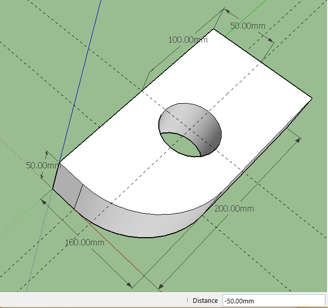
and hit enter. this will make a hole in the center.
Orbit your model just to prove it
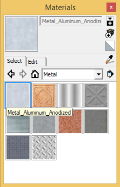
Let us give it a texture. Hit b key to bring the bucket tool. This will open a window called "Materials".

Choose "Metal" from the drop-down menu and click on Metal_Aluminium_Anodized
Click on the sides. Select another texture and click on other sides as you like.

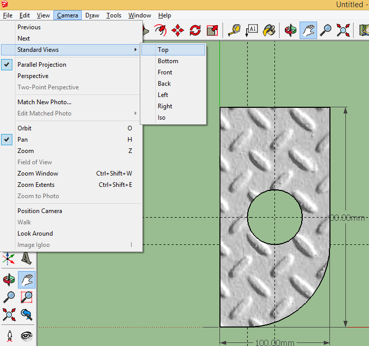
You may like to present your model on orthogonal drawing (Top, Side, Front, Iso views). Well here is the hint...
First click on "Parallel Projection" under Camera view and then select any view you like