PicAXE 14M2
In this tutorial we will ...
- first learn to program PicAXE's 14M2 chip using an experimental board and some input/output devices
- build a vehicle using PicAXE's 14M2 chip and L293D motor driver IC.
This is a good entry level project for engaging mechatronics (mechanical + electronics) students.
Step 1: Get the required items:
Software:
- Go to www.picaxe.com and download "PicAXE Editor" software and install it. Do not worry it is absolutely free. It has some inbuilt help guides which are very useful.
- Download the AXE027 drivers and install them before you connect the PicAXE cable. This are essential as this is the only way PicAXE can communicate with the computer.
- installing drivers can be bit tricky. You need to check that they are installed properly in "Device Manager". If anything has an "!" mark in front of it means that it is not installed properly. Right click the item and click on "Update" and choose the path where you have saved the drivers. You will have to do it couple of times until all "!" marks are gone.
- Pebble is a breadboard emulator that is also available for free download. This is useful for designing the circuit on breadboard on computer without messing around with components.
Hardware:
- Integrated Circuit: PicAXE 14M2, L293D motor driver, Sony IR module - TSOP1836 - 38KHz,
- Resistors: 22K, 3 x 10K, 3 x 330 ohms, 4.7K
- Capacitors: 4.7uf - 10V, 0.01uf - 50V, 100uf - 10V
- Diode: IN4001
- Others: Small speaker, LDR (light Dependent resistor), DPST Tactile Switch also known as Momentary Switch or MOMS, Stereo socket (PCB friendly!),
- Equipment: PicAXE download cable, Breadboard, Veroboard, Connecting wires, solder, 3 x AA Battery pack with switch, Timaya Gearbox, Ball Caster, Base plate and wheel set, Universal TV remote control set as Sony TV remote control
- Tools: Wire stripper, soldering iron with stand, side cutter
Step 2: Prerequisite
The first lesson on theory should be dedicated to previous knowledge testing/refreshing/updating. Students need to learn...
- the symbols of electronic components (LDR, resistor, capacitor, diode, LED, Speaker, DIL 14/16 pin IC, motor, switch, sony IR receiver module)
- to read and understand circuits
- the method of finding the values of resistors and capacitors, their functions.
- the function of an LDR and a Speaker.
- about different types of switches (SPST, SPDT, DPDT) and how they function.
Step 3: Learning theory
Let us now learn the pin configuration of 14M2 so that we can find out different purposes a particular pin can be used for.
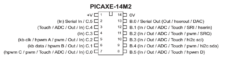
Power Supply: Use a 3xAA cells battery pack with switch only.
All pins C.0, C.1, C.2,C.3, C.4, C.5 and B.0, B.1, B.2, B.3, B.4, B.5 can be used as inputs and outputs. So it is a good idea to set them as inputs or outputs in first few lines of your programming. We will talk about this later in this tutorial.
Outputs: Use LEDs or a very small speaker like ones used in greeting cards. Motors will not work directly. For that you will need another IC (L293D). That is a separate article that you can find using search feature on this website.
Inputs: Any input device/sensor can be used like a Switch or an LDR. Make sure that the inputs are connected to 0 Volts supply via a 10k resistor.
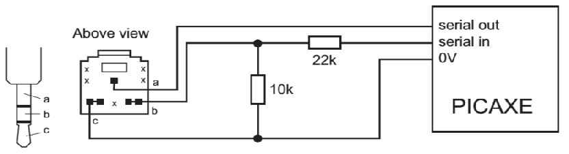
C.5 or Serial in pin: Always use the 10k and 22k resistors as shown below, even if the chip was programmed on a different board.
Step 4: Construction
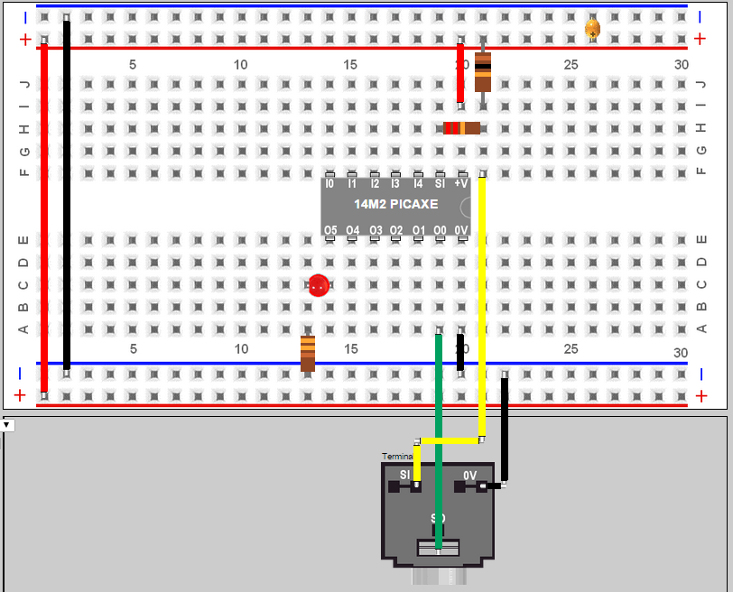
Let us use breadboard emulator called "PEBBLE" that we have downloaded (see step 1)
![]()
You can set the breadboard by choosing from bottom left drop down list. Do not worry much if you cannot find it as we will magically do it now.
Now get ready for some magic. Click on the "Save/Load" button. It is in the lower left area. Delete everything from the window that pops up. Copy paste the following code into it and click "Load Circuit" button. Click "OK" to clear any preexisting components on the breadboard.
You should see the following circuit. Great, now assemble the circuit on a real breadboard and connect the battery pack (3 x AA with switch) anywhere on the red and blue rails. The positive of the battery pack is to be connected to the red rail and the negative of the battery pack is to be connected to the blue rail.
Open "PicAXE Editor" Notice that PICAXE 14M2 is selected. There is nothing under the COM port. If this is the case then you need to install the COM port drivers again (see step 1)
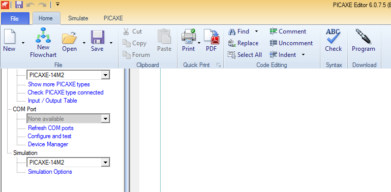
Open a new file by clicking on the "New" icon. Copy and paste the following code into this new file.
Load the program on the PicAXE by clicking on the "Program" icon. The LED should start blinking once the program have successfully loaded on the microcontroller.
This concludes your step 4 as you have successfully programmed the microcontroller.
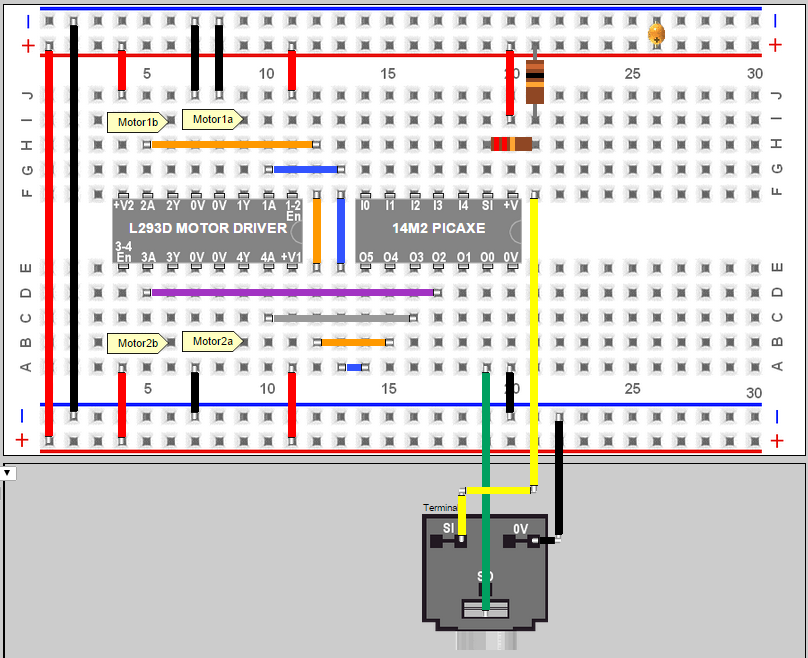
Step 5: Bring in the motor driver IC L293D
Now let us go back to the PEBBLE emulator and copy paste the following code using the "Save/Load" button (it is on the left side of the emulator programming window), to bring in new components on the breadboard
This is what you should get...Great, now assemble the circuit on a real breadboard and connect the battery pack (3 x AA with switch) anywhere on the red and blue rails. The positive of the battery pack is to be connected to the red rail and the negative of the battery pack is to be connected to the blue rail.
Open "PicAXE Editor" Notice that PICAXE 14M2 is selected. If there is nothing under the COM port then you need to install the COM port drivers again (see step 1)
Open a new file by clicking on the "New" icon. Copy and paste the following code into this new file.
Load the program on the PicAXE by clicking on the "Program" icon. The LED should start blinking once the program have successfully loaded on the microcontroller.
This concludes your step 5 as you have successfully programmed the microcontroller.to run two motors
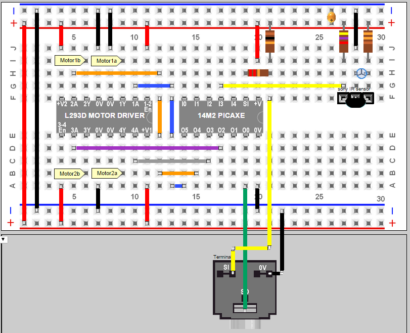
Step 6: Bring in the infrared sensor for remote control
Now let us go back to the PEBBLE emulator and copy paste the following code using the "Save/Load" button (it is on the left side of the emulator programming window), to bring in new components on the breadboard
This is what you should get...Great, now assemble the circuit on a real breadboard and connect the battery pack (3 x AA with switch) anywhere on the red and blue rails. The positive of the battery pack is to be connected to the red rail and the negative of the battery pack is to be connected to the blue rail.
Step 7: Remote controller
Before we write the code and load it on PicAXE we need to first program our remote control and device a method to find out the codes for each button that is generated when it is pressed.
Programming a universal remote control is easy as you just have to follow the steps that is in the instructional manual that came with the remote control.
Finding the code that is generated by pressing a button is also very easy. Just load the following code on PicAXE module, that we constructed in previous step, and a new debug window will popup because of the line "debug b0". Your job now is to note down numbers next to "b0" when you press a button. Making a table as follows is helpful.
| Button Pressed | Code Generated |
| Channel 1 | 0 |
| Channel 2 | 1 |
| and so on... |
We will use these codes in programming in the next step.
Step 8: Remote control - Basic coding
Open "PicAXE Editor" Notice that PICAXE 14M2 is selected. If there is nothing under the COM port then you need to install the COM port drivers again (see step 1)
Open a new file by clicking on the "New" icon. Copy and paste the following code into this new file.
Set up a Universal TV remote control as a Sony TV remote control. All universal remote have a set of instructions with them about this. A typical example of this is as follows...
Press "SET" button and "TV" button together and let go. the RED LED will turn ON, now key in the numbers 077 slowly. The LED will flash after each number and will turn OFF after last number is entered indicating that the number has been accepted.
Load the program on the PicAXE by clicking on the "Program" icon. The motors should start rotating on pressing 2 and stop on pressing 5 blinking once the program have successfully loaded on the microcontroller.
This concludes the step as you have successfully programmed the microcontroller to accept remote operation and run motors.
Step 9: Advanced coding
The PicAXE microcontroller (or any other) has limited number of lines. Our program should not exceed that limit else the extra lines will simply be truncated. So our goal should always be to write the program in least number of lines. Let us consider one example. Suppose we want to switch all B pin outputs to High and pause for 5 seconds before we pull them down to Low. The code will be something like...
But we can write the same code in two lines. For that we will have to first declare which pins are being used as inputs and which ones as outputs. To do that we write two lines at the start of the program as follows...
Let dirsB = %111111
Let dirsC = %000000
this will set all B pins as output pins and all C pins as inputs.
then later in the program anywhere we can use "Let pinsB" command to set the outputs. For example Let pinsB = %110000 will set B.5 and B.4 to HIGH and B.3, B.2, B.1, B.0 to LOW. Note that the order is % B.5 B.4 B.3 B.2 B.1 B.0